Description
This project combines a GPS receiver module, a Microchip PIC microcontroller and a Secure Digital memory card to make a GPS data logger.With a large capacity and reasonably long battery life it is a very useful device for logging GPS position for example for mapping with OpenStreetMap.
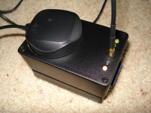
In this picture the complete GPS data logger can be seen. On the top right hand side from front to back are:
- The status LED which shows the current GPS fix status. It is off until the PIC has synchronised with the data sequence, red when the GPS module has no position fix, orange when it has 2D fix and green for full 3D fix.
- The wake/sleep switch; push to start and push to stop. Hold down for 10 seconds when starting to reset the write position to the start of the SD card.
- The MMCX antenna connector with the external antenna connected (the antenna itself is resting on top of the box).
- The GPS LED (showing green, barely visible behind the antenna connector). This lights green when the GPS is powered and flashes orange when there is data being transfered.
- The SD card LED (showing green). This lights green when the SD card is powered and flashes orange when there is data being transfered.
The overall size of the complete unit is 75mm long, 50mm wide and 45 mm tall (27mm for the top box and 18mm for the 3xAA battery box).
Performance
The data from the GPS is logged every second with the raw NMEA sentences being written to the SD card. The data written to the card is the GSA, GGA, RMC and GSV sentences which by excluding the carriage returns this should never exceed 512 bytes per second. The data contains:- GGA - 78 bytes - time, fix, lat, long, altitude, horizontal dilution of precision.
- GSA - 69 bytes - fix (none, 2D, 3D), satellites used, dilution of precision.
- RMC - 78 bytes - time, lat, long, speed, course, date.
- GSV - 74 bytes - satellite information (4 messages).
The power consumption in standby is 0.6mA which means that the theoretical life is 4 months which would probably exceed the self-discharge time of the batteries.
I have been using a 512MB SD card which allows for storage of 1 million data points which is more than 11 days. Any capacity card up to 2GB could be used without a change to the software.
Pictures
Inside the Box
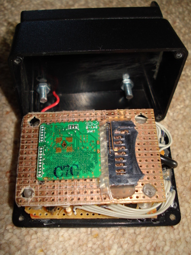
With the main box opened the contents can be seen with the bottom of the lower PCB visible on top. The base of the GPS module is on the left, the connectors fit through a hole in the PCB. The SD card socket is on the right with the connections through the PCB underneath the glue holding it to the PCB.
The holes in the PCB fit over the bolts in the bottom of the box that bolt this box to the battery compartment. The top PCB has similar holes and fits over bolts glued to the lid of the box. Between them (fitting over the end of the bolts) are lengths of plastic tube as spacers.
Exploded View
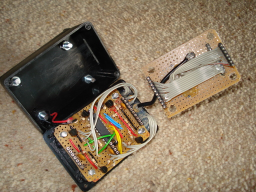
With the PCBs disassembled the contents are clearer. The two PCBs are connected by ribbon cables and 0.1" SIL plugs/sockets (10-way for the GPS and 7-way for the SD card). The black cable still connecting them is the GPS module antenna connector to the MMCX socket on the lid of the box.
Top PCB
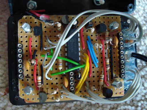
The PIC microcontroller is in the middle of the top PCB with the components arranged around it very much like in the circuit diagram. The SD card components are generally on the left and the GPS module components on the right. The ICSP programming connector is at the bottom and the voltage regulator at the top.
The LEDs and switch are glued to the inside of the top of the box with wires to the PCB. The MMCX connector is also glued on with a cable to the GPS module.
Software
The PIC software is written in assembler and based on earlier projects using RS232 and SPI interfaces. The RS232 part receives data from the GPS module and the SPI part writes it to the SD card. In between there is time to look at the data and flash the LED red, orange or green depending on how good the GPS position is (no fix, 2D fix or 3D fix).The PIC runs at 8 MHz using the internal oscillator. The RS232 receive and transmit functions operate at only 9600 baud and the SD card writes at 500 kbps. There are no interrupts used because there is lots of time to receive the data from the GPS and write it to the SD card. The sleep function does use the switch to interrupt it and wake up when it is sleeping. When it is operating the switch interrupt is disabled and the flag is polled once per cycle.
The data is written to the SD card in blocks of 512 bytes (the native SD card block size). One block is written each second and padded to 512 bytes with zero bytes. Starting and stopping is recorded by a blank block in the SD card. There is no file system on the SD card so it needs to be read byte by byte (easy in Linux using a USB adapter and reading the raw device). To read the card I have a simple C program that extracts the NMEA data and writes one file for each time that the box was awake.
The complete information for this project is available for download. This includes the library functions for the RS232 and SD card interface as well as the circuit diagram, layout diagram and various C programs. This project is included in the library of PIC code that is available for download.
Circuit Diagram
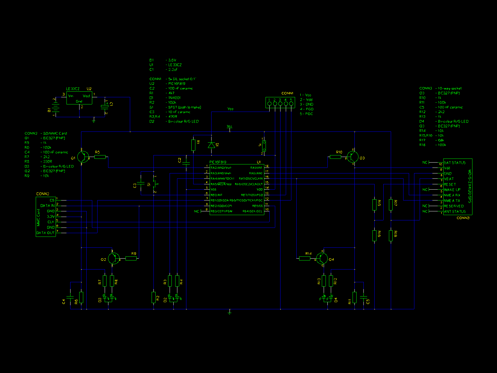
The circuit diagram shows all of the components. The PIC is in the middle, the SD card on the left, the GPS on the right and the rest around the PIC.
The SD card circuit consists of a transistor to turn the power on and off under the control of the PIC, SPI connections to the SPI pins on the PIC and a second transistor to drive the LED from the data in line on the SD card.
The GPS module circuit is very similar to the SD card circuit with a transistor for the power and another for the LED on the RS232 TX line. The RX and TX connections go to the PIC as does the reset line. The battery backup input for the GPS module internal memory comes from a simple resistor divider to get between 1.5V and 2V.
The PIC is a 16F819 device in a 18 pin package. The whole circuit runs on 3.3V which is provided by the LE33CZ low drop voltage regulator at the top left. A jumper is provided to isolate the PIC power supply so that 5V from the ICSP connector can be used when programming it (after disconnecting the GPS and SD card!). The wake/sleep switch is used to put the PIC to sleep or wake it up, there is no on/off switch.
Circuit Layout
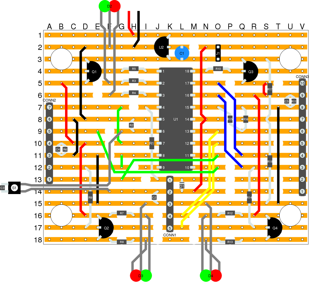
I drew this PCB layout diagram to help with the placement of the components. It only just fits on the PCB with some unusual wiring in places.
Components
The GPS receiver that I used is a ZX4120 GPS Module which I bought from Crownhill Associates. This is a very small device, measuring just 26mm square and 3mm thick. As you can see from the pictures it takes up only a small part of the total space. This module operates at 3.3V and provides a bidirectional RS232 type interface at that voltage. Other connections are power and ground, reset and a memory backup voltage as well as the GPS antenna.I also bought a GPS antenna from Crownhill Associates although any antenna with an MMCX connector that operates at 3.3V would work.
The SD card socket was bought from Toby Electronics and is the simple type that doesn't eject the card for you.
Other non-trivial parts were the MMCX socket for the antenna, the 0.05" pitch SIL socket for the GPS module and the 3.3V low drop voltage regulator. All of these parts (and most of the others) came from Rapid Electronics.