Description
This project uses a Microchip PIC microcontroller and an Infra-Red LED to act as a PC controlled cable TV changer.Operation
The purpose of this is so that my MythTV Personal Video Recorder (PVR) can change channels on the cable TV set-top box when making a recording. A very simple program on the computer sends the channel number over RS232 to this PIC based IR transmitter which creates the correct waveform for the digits to be sent.The cable TV box is very old and uses an unusual coding format that I haven't seen described elsewhere and which doesn't seem to be covered by most programmable remote controls. By capturing the signals it was possible to decode them so that the correct signals can be generated for the digits.
The function itself is very simple with just a PIC with a serial interface and an LED that is switched by a single transistor switch to provide sufficient current. I am using a very nice FTDI USB to serial converter cable (TTL-232R) that provides 5V TTL levels as well as the 5V power supply for the circuit.
Pictures
Complete Unit
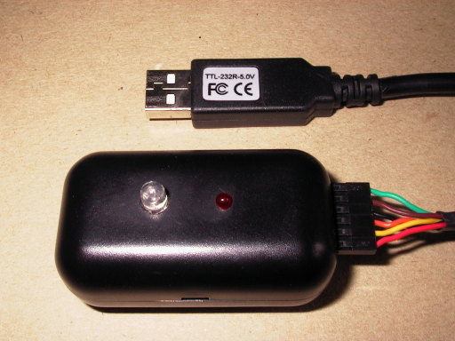
In this picture the box can be seen with the Infra-Red LED and a smaller red LED visible. The USB connector is at the top of the picture and has all of the RS232 converter electronics are built in to the connector which makes a very nice package.
The overall size of the box is 50 mm long, 30 mm wide and 20 mm tall.
PCB Inside
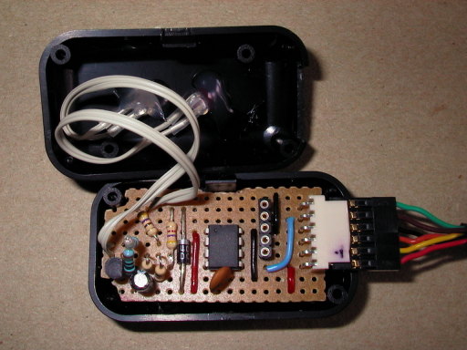
The circuit inside the box is very simple with just the serial connector (on the right), the ICSP socket (5-pins on right of IC), the PIC device in the centre and the transistor switch in the bottom left. The Infra-Red LED is glued to the inside of the top of the box along with the red LED and there are various resistors for these on the PCB.
Software
PIC Software
The PIC software is written in assembler and has just an RS232 interface waiting for data which it then transmits by switching the Infra-Red LED on and off. There is a small amount of processing to convert the incoming digits to 17 bits of data and thence to Infra-Red pulses.The PIC is a 12F675 device and runs at 4 MHz using the internal oscillator.
The Infra-Red LED is modulated at 38 kHz (26 microseconds period = 26 instructions) while it is "on" which is a common remote control frequency. The data is transmitted with fixed length "on" periods (~700 microseconds) but different "off" periods for one (~4300 microseconds) and zero (~2100 microseconds) and a start bit "on" for ~9000 microseconds.
The complete information for this project is available for download. This includes the library functions for the RS232 interface and IR transmission as well as the circuit diagram, layout diagram and various C programs. This project is included in the library of PIC code that is available for download.
PC Software
To control the device there is a very simple program that sends the digits to be transmitted down the serial port (in this case the USB device). This is run from a script that MythTV runs just before starting to make a recording.Circuit Diagram
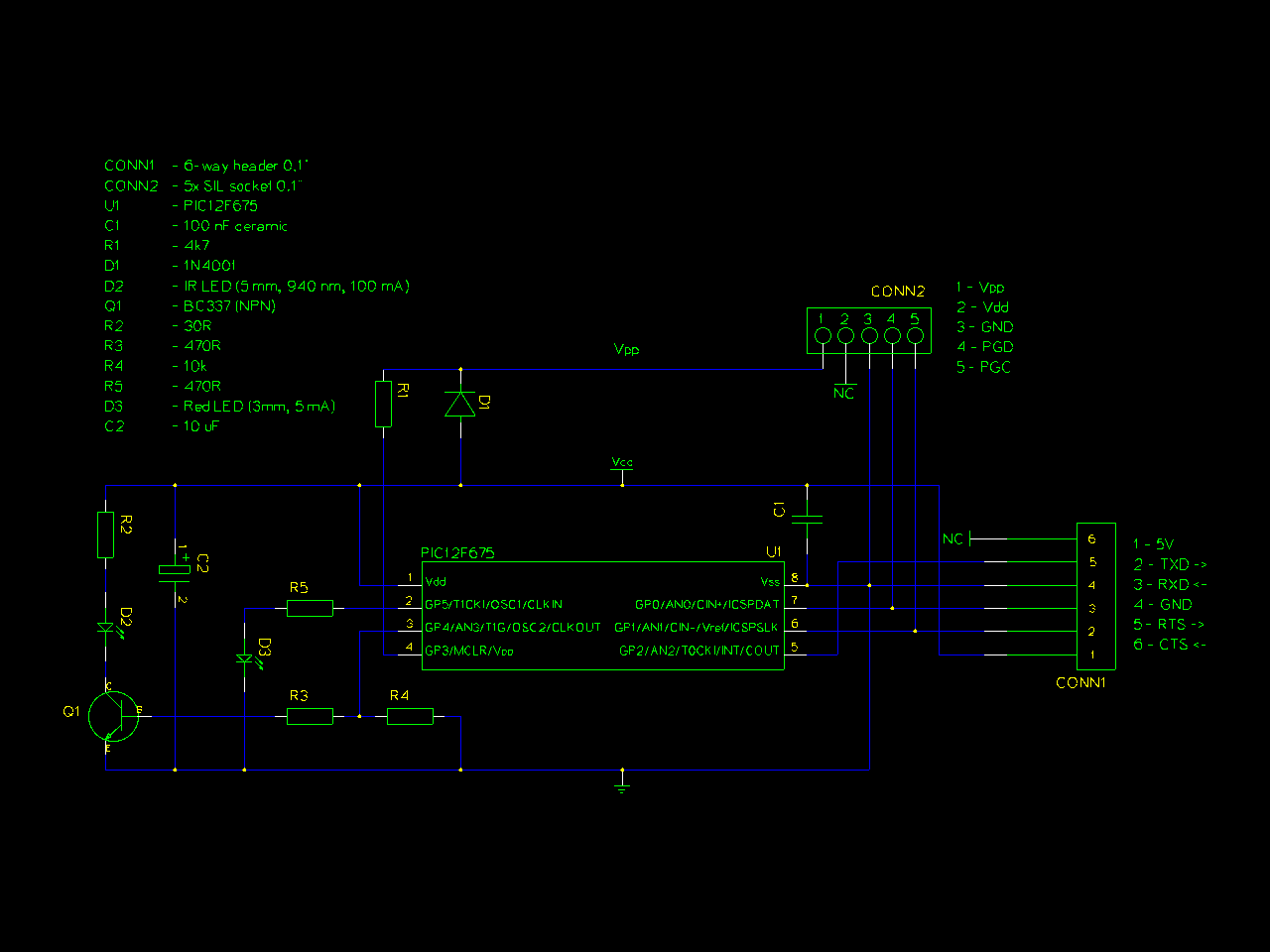
The circuit diagram is very simple with only a few components.
Circuit Layout
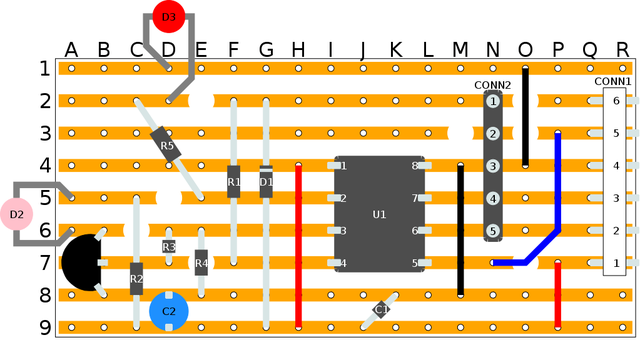
This simple PCB layout diagram shows the placement of the components.
Note: this is different from the version in the downloadable file because it contains a correction for the placement of component R5.