Description
This project uses a Microchip PIC microcontroller, a serial EEPROM and a thermistor to create a temperature recorder.Performance
The temperature is measured and stored at user programmable intervals; this can be from 1 second to 256 seconds. The time interval is set by programming it and the start time into the EEPROM.Most of the time the PIC will be asleep and the EEPROM IC is inactive. This gives a very low current consumption of approximately 50 uA or about 1 mAh per day.
The EEPROM used is 32kBytes which can store up to 32,000 measurements. This could be one measurement every 30 seconds for 11 days for example.
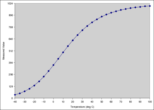
The combination of thermistor and analogue circuit gives a range of between about -40 °C and +100 °C although the linear range is between about -10 °C and +40 °C.
At any time the device is either measuring the temperature and writing it to the EEPROM using the I2C bus (when the thermistor is connected) or not using the I2C bus so that it can be accessed directly to be read (when the thermistor is not connected).
Pictures
Complete Unit
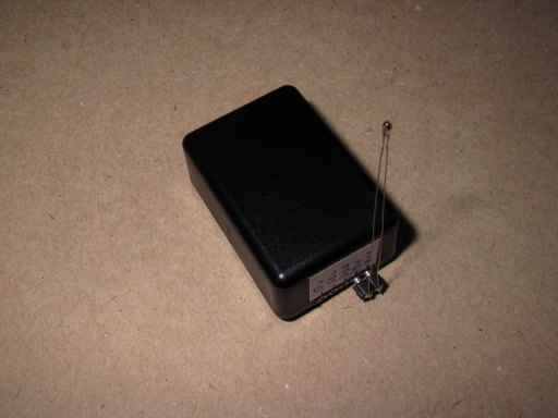
In this picture the temperature recorder can be seen with the external thermistor plugged in. The connector on the end contains power, I2C clock and data and analogue input.
The overall size of the complete unit is 40 mm long, 26 mm wide and 16 mm tall.
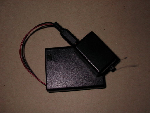
In this picture the temperature recorder is connected to a battery pack with 4xAAA batteries. This gives a good indication of the size and shows that I need a much smaller set of batteries.
PCB (version 1)
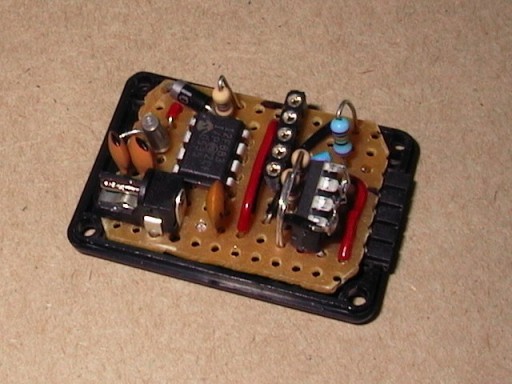
The first version of the circuit is built on stripboard with DIL packaged ICs and conventional through-hole passive components.
The PIC microcontroller is to the left of centre on the PCB with the EEPROM IC mounted vertically to save space on the right of centre.
The external connectors are the 1.3mm power socket on the bottom left and the 5 pin SIL socket on the right.
The other components are the ICSP socket with resistor and diode at the top left, crystal oscillator and two capacitors on the left of the PIC, the two I2C pull-up resistors next to the EEPROM and the resistor for the thermistor potential divider at the top right.
PCB (version 2)
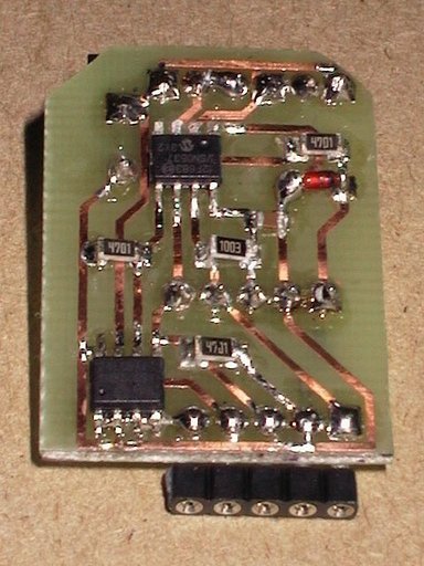
The second version of the circuit is built on a homemade single sided PCB with SO8 packaged ICs and surface mount passive components.
The ICs have a pitch of only 0.05" (1.27 mm), the decoupling capacitor is an 0805 package (0.08" by 0.05" = 2 mm x 1.27 mm) while the resistors are in a 1206 package (3 mm x 1.5 mm). The crystal and its capacitors are the same as before as are the connectors. The tracks are all routed with 0.02" width (0.5 mm) although in the final production they have come out slightly wider.
Software
PIC Software
The PIC software is written in assembler and based on earlier projects using I2C interfaces. The EEPROM, PIC and external connector all share the same I2C bus and the PIC will not use it unless the thermistor is fitted. The EEPROM address keeps incrementing in this case so that breaks in the data can be seen.When the temperature measurement is not being made the PIC goes to sleep. It is woken once a second (using an external crystal oscillator and internal counter) to check if it is time to make a measurement. The sampling interval is stored in a fixed location in the external EEPROM and is read at power up.
The thermistor and a resistor form a potential divider that is measured by one of the ADC channels on the PIC. This is measured four times and the four results are added together. This gives a slightly better measurement since the average of four readings is likely to be closer to the true value than a single measurement alone due to the noise present in the circuit.
The ADC measurement is stored directly rather than being converted to a temperature first. To save space and maintain accuracy the change from the previous measurement is stored in 1 byte when possible, otherwise 2 bytes are used. If the value has changed from last time by between -112 and +112 then the amount of the change is stored. If the value has changed more than this then two bytes are stored with the first byte having flag bits to indicate this.
The PIC is a 12F683 device and runs at 4 MHz using the internal oscillator. The I2C interfaces run at nearly 100 kHz using bit-banging (programmed control of the I/O lines) and not a PIC SSP interface.
The complete information for this project is available for download. This includes the library functions for the I2C interface as well as the circuit diagram, layout diagram and various C programs. This project is included in the library of PIC code that is available for download.
PC Software
To reset the device there is a program that wipes the entire EEPROM (to 0xff) and writes a 32 byte header with the time and the sampling interval. The PIC will use the sampling interval to decide when to make a measurement and the start time is used by the program that extracts the data.To read the data from the PIC there is software that dumps the entire EEPROM contents and extracts the start time, step size and raw data. The data is converted to date, time, measurement value and temperature for each data point in the EEPROM.
Circuit Diagram
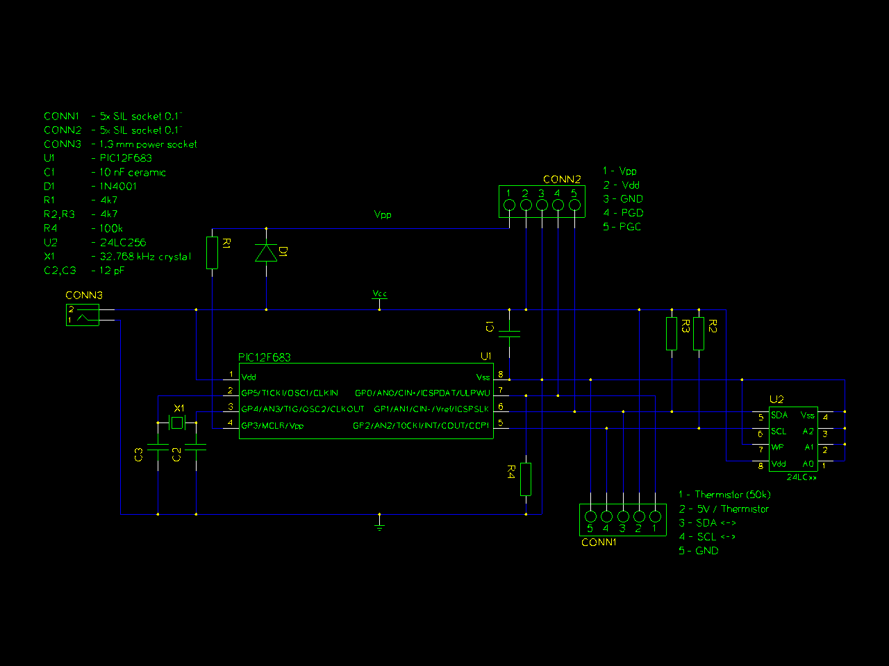
The circuit diagram is very simple with only the ADC interface (one resistor), I2C interface (2 resistors), EEPROM IC, ICSP (socket, 1 diode and 1 resistor), oscillator (crystal and 2 capacitors).
Connector 1 contains the I2C interface for reading the data back from the EEPROM (SDA and SCL) as well as an optional power supply. When measuring the temperature the thermistor is connected between pins 1 and 2.
Connector 2 is the PIC programming connector.
Connector 3 is the power supply used while measuring the temperature.
Circuit Layout version 1
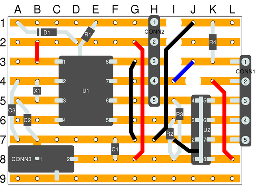
This simple PCB layout diagram shows the placement of the components on the stripboard. The view is from the top of the PCB, the same as in the photograph.
Circuit Layout version 2
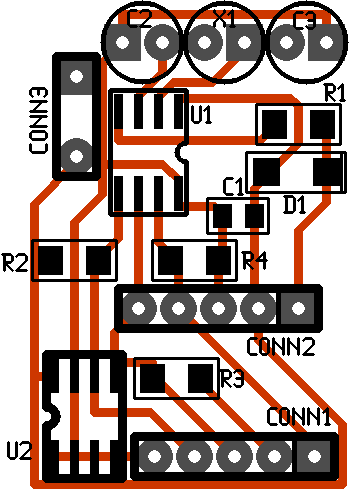
This PCB layout diagram shows the components and the tracks on the custom PCB. The view of this PCB is from the side with the tracks although some of the components are mounted on the other side.
Components
None of the parts for this project are difficult to find although the surface mount components are less common than the standard ones.Example Results
The image below shows an example of the results that can be obtained with this device.
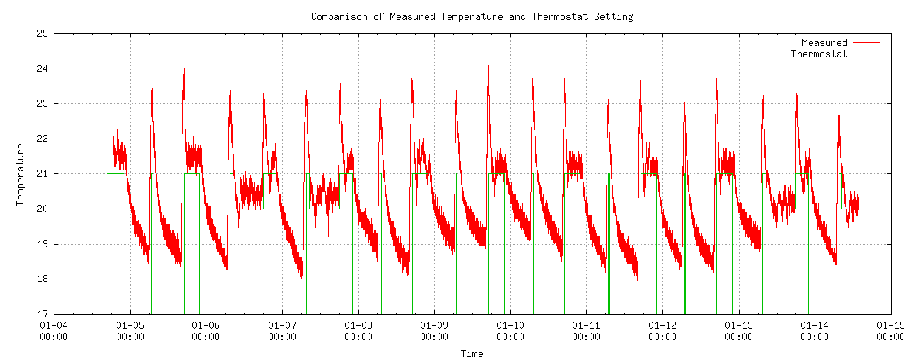
The temperature logger was placed next to a household thermostat for a period of about 10 days in the winter at the start of 2007. On the plot are shown the measured temperature and the thermostat settings (an "intelligent" thermostat that aims to reach the target temperature at the specified time). The measured data clearly matches the thermostat setting for the time that the heating is active and during the day and night that it is inactive the temperature drops rapidly.