Description
This project is a Microchip PIC microcontroller with an RS232 serial interface on one side and an Infra-Red receive and transmit interface on the other.Important - All mention of RS232 on this page actually refers to RS232 waveforms operating at 5V TTL levels not +/-12V levels which would destroy the PIC device. An appropriate converter between the two must be used.
By sending commands on the RS232 interface it is possible to receive or transmit a sequence of bits modulated as a series of on/off states in a 38 kHz infra-red carrier signal. Infra-Red remote controls use a carrier signal (typically around 38 kHz) so that there is no confusion with sunlight etc. The carrier is turned on and off to represent the bit sequences at a lower rate, for example 500 Hz).
Either a raw sequence of on/off states can be captured or transmitted or one of a predefined set of remote control formats can be emulated (receive or transmit).
Pictures
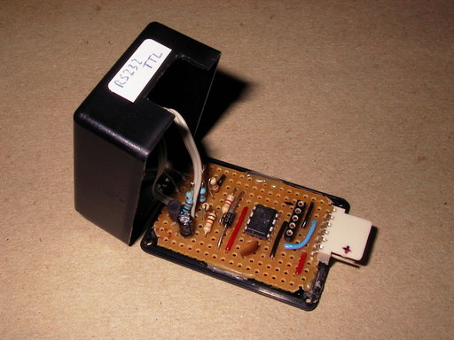
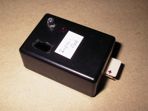
The circuit is built on stripboard with a DIL packaged IC and conventional through-hole passive components. The PCB is glued into the base of a small box for convenience.
The PIC microcontroller is the only IC and mounted approximately in the centre of the PCB. The RS232 connector is on the right with the Infra-Red receiver and LED for transmit on the top. Rather than use a photo-diode and decoding the signal a complete module (in this case a TSOP1738 photo module) is used. This contains all of the circuitry to detect a signal with a carrier frequency of 38 kHz.
PIC Software
The PIC software is written in assembler and this project was the development platform for the Infra-Red library functions.The complete information for this project is available for download. This includes the library functions for the RS232 and IR interfaces as well as the circuit diagram, layout diagram and various C programs. This project is included in the library of PIC code that is available for download.
Circuit Diagram
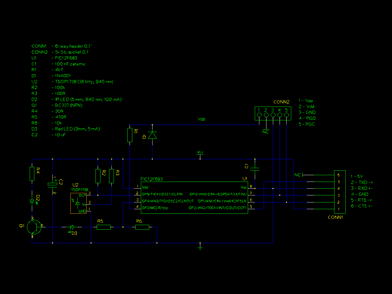
The circuit diagram is quite simple with the RS232 interface (a connector), PIC (IC and decoupling capacitor) and ICSP (socket, 1 diode and 1 resistor). For the Infra-Red part it is more complicated. There is a transistor (operating as a switch) and a capacitor to ensure that sufficient current can be switched to drive the LED. Driving the LED with the PIC alone would not allow enough current to transmit a strong Infra-Red signal. There is also a small red LED to show when the Infra-Red one is operating.
Circuit Layout
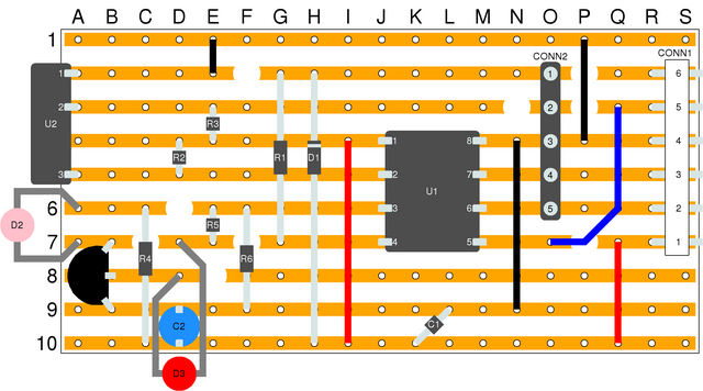
This simple PCB layout diagram shows the placement of the components on the stripboard. The view is from the top of the PCB, the same as in the photograph.